
This page is now maintained through my main site at NViRT.
Please visit the NViRT article here to comment: http://nvirt.com/2006/11/28/making-practical-wii-component-cables/
These are the original instructions from the cable I built. If you copy this howto at least give me credit.
Using a buds component cable I duplicated the pins with a regular AV cable from nintendo. My cable is switchable so that it is both component and composite at the flip of a little switch.
Spellcheck Rox.
*Updated Dec 20th 2006*
Thanks Andrew
Thanks Jx7 ;)
*Updated Aug 20th 2007*
Moved site to NViRT
http://nvirt.com/2006/11/28/making-practical-wii-component-cables/
What you'll need
- Pin out diagram New (nearly) complete pinout from nfg.com wiki
- Wii AV cable from store.nintendo.com (2 if you don't want to use the Wii supplied set) Here
- Soldering Iron w/ all the fixin's (*)
- Electrical Tape (*)
- Shrink Tubing (*)
- Knife
- Wire Cutters (or scissors if your ghetto)
- Small SPST or SPDT Toggle Switch (**) example
- Extra length of two strand copper wire. (Light gauge but not too light) (**)
- Cardboard (or a Wii... Youll see.)
Stuff marked (*) is optional but required for a good job. The line item marked (**) is required if you want to toggle between composite and component without taking apart the cable.
1. Pop open both cables. Decide which set is going to be components.
Popping open the Cable Connections is pretty easy... just slide the tip of the knife in the seam located on the face of the connection (where black meets grey) ...
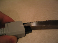
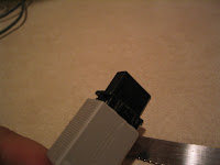
...and pry a bit. Not too hard so that it bends the grey plastic out of place, the whole box flexes enough to remove the casing without destroying it. If you happen to destroy on of the cases that's fine.. you just decided that one is your component set. (You may need two knives to get both clips lose. Slide on in on one side to guide the clip off and pry the other side.)
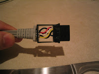
2. Start pulling pins on your "component set". (READ!)
I feel this is where people will have the most problems. The pins where designed to stay in place once set so there are a few little speed bumps to pulling these pins. You will be presented with 6 pins. R audio sig, R audio G, L audio sig, L audio G, Composite sig, and composite G. *All Grounds are common* Best Pin to work with first is 12 (Composite G).


Cut a peice of cardboard wide enough to fit into the connector but still long enough to remove. This is extremely important. If you dont have cardboard then continue reading.
First use your finger tips and pull on the wire only hard enough to break the clip free. I recommend a pinching/prying against the connector as not to exert force after the clip is free.

you only want it to move about 1 cm. Once its "free" you'll notice that it will not come out entirely unless you have the carboard jammed in the connecter end. DO NOT PULL IF THE PIN DOES NOT FREELY MOVE. you do not want the clip coming down on its back stop and bending! If you dont have cardboard handy then push the clip back into place a bit (NOT ALL THE WAY) and insert the connector into your otherwise disconnected Wii. This resets the pins back so that they will not catch the back stop when you pull. NOW PULL GENTLY!. If the pin does not just slide out then its still catching the back stop. If this is the case, use thicker cardboard.
Repeat for the rest of the pins. (yea... you fingers will hurt. Don't resort to pliers you'll only break wires and bend/destroy pins)


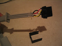
Remove cable pinch guard thingy and box casing from your component set if you have not already. You should be left with a set of cables with a small metal bracket and pins... nothing else.
3. Prep Cables Together
- On the composite set, ONLY remove the flexy pinch guard thingy ONLY. Leave the casing on your composite set. On your component set (the set that is just wires and pins ATM) Feed all the pins through the composite cable set's casing so that you have two sets of cables through the same hole. (you will have to maneuver the metal bracket through one side at a time.. it is possible. don't break it off. be patient. you ll want it there.)
- LABLE THE LINES FOR VIDEO, AUDIO L, AUDIO R, AND COMPONENT SET!
4. Prep pin sets
- Start warming up you soldering iron for the next step if you want to use one (recommended but not required). You will NOT cut any composite cable lines. You will however want to cut the black ground lines on your soon-to-be Y, Pr, Pb lines. ONLY THE GROUND LINES. Sorry, had to make that clear. On the 3 black ground lines on the component set, cut the G wire half way between the main grey sheath and where the G wire meets the pin. You want to leave enough wire on both ends. You'll have 3 loose pins now.. set these aside and make sure they aren't bent out of shape.
5. Set mode Pins
- Take 2 of the loose pins you just cut off. Strip a small amount of the sheath off both. Take a look at the composite (or empty block from the set you took apart) and get acquainted with the pins. The diagram from http://nfggames.com/wiki/doku.php?id=av:wii_multi_av_pinout is numbered from looking at the back of the connector (use existing pins to relate if I'm not making sense at this point). Find where pins 8 and 10 should go on the pin block of the composite set your working with. feed the 2 loose ground pins into these spots spring pointed in to the center. Make sure not to put these in backwards. The pin should easily slide in and make a small click into its grove. This small click was the pin coming off the back stop. Now you want to set the pin the rest of the way into is spot. Use the tip of the knife if you need to to press the pin as far as the rest. You should now have 2 lines into pins 8 and 10.
- This is where you decide if you want component cables or a hybrid switchable cable. If you want just component cables then you want to jump pins 8 and 10. This tells the Wii that the cable is component capable. Twist and solder together or twist some copper to connect pins 8 and 10 together. Wrap with a small amount of electrical tape or shrink tube the tip.
- If you want a hybrid set, Solder (or twist) a ~6 inch section of the the two lead copper cable to the two 8,10 pins. Basically you are going to extend the jump. Tape or shrink tube the points. Run the two lead copper line back out the connector casing. You will solder a switch to this that will be accessible on the outside of the cable when its all put together. Read below in the Addendum for further instructions for completion of the switch. (final step)
6. Set signal pins.
- So now you have a component capable connector. Time to set the component signal pins. Find pin slots 7, 9, and 11, which are Y, Pb, Pr respectively. When using standard AV cables for component sets i like to use Yellow for Y (Green on component jacks), Red for Pr (Red anyway) and White for Pb (usually blue). So set the yellow lead pin into 7, White into 9, and red into 11. All you need to do now is ground the component signal grounds.
7. Grounding component signal grounds.
- All grounds are common. I prefer to use the composite video ground (pin 12) for this part. There is a couple ways to do this.
- If you are making pure component and don't wish to ever use composite with these cables (without more work), then just cut the composite ground on the main sheath side (opposite the pin) and twist the component grounds to the now open pin 12 and optionally solder (recommended, as usual).
- If your making a hybrid switchable cable then include the composite ground as well. May require some work but I had enough line left over to easily solder in.
- Either way you want to tape and/or shrink tube the lines
- Visually inspect your new connector. Make sure you don't have any lines exposed and touching (except grounds). Make sure there is no bent pins inside the connector. Look for stuff out of the ordinary. remember your building a permanent solution here. Not only that but there is voltage running through the AV out. Blow up your Wii or your TV... let alone both.
- If everything is double checked then pop in connector and hook up to TV.
- If you are making a hybrid cable, and you have not yet already hooked up the switch.. temporarily twist the other end of the two lead copper line.
- TEST! Turn on the Wii make sure mode pins (8 and 10) are jumped if its a hybrid cable and set the Wii to 480p in options/screen resolution.
- See Trouble shooting section if your having issues at this point.
9. Final assembly
- Snap casing back on the black connector having the two metal brackets on the cable push pack on the inside of the housing. Keep an eye on internal connections and make sure they dont bend to a point of breaking or shorting out.
- If you are attaching a SPDT switch to the mode pins, solder one of the two lead lines to the middle pin on the switch and the other to one of the side pins. Leave one of the side pins untouched. SPST switches only have 2 leads (self explainitory I'd hope). http://en.wikipedia.org/wiki/Switch#Contact_arrangements
- Mount the switch on the cable with tape or something creative like dremmel a spot for it in the housing if you dare. Just keep in mind the orientation of the cable when its hooked up to the Wii.
10. Completed product.
- You should now have a cable worthy of prolonged use. Have fun in 480p! :) ... Let me know if they work out for you.


